Omorgan 1 1 Cars Posted Saturday at 01:08 PM (edited) Hello all. Again it's me with more questions about spark and fuel. I have spent 2 weeks reading and trying to get spark and fuel based upon your guys previous help and the rest of the topics. I have read and annotated multiple different wiring diagrams etc to no avail. After I got the car started last time thanks to @DamirGTI, @welshpug, @SRDT and @petert, it spun a bearing first drive and I tore it down to find some chimp had assembled it and it was never going to run for long. (wrong crank, stem seals not on the guides, loose guides, main-cap bolts hand tight etc) I've rebuilt the engine and now I am at the stage again where I have no spark or fuel. I've changed the TDC sensor and I have a blue top ignition amp. Last night I stripped the loom and have taken notes of every wire and plug and where it goes into the ECU socket. I cant find a diagram for my ECU that is accurate to my two row ECU (Bosch Motronic 0261 -200 - 125) As I don't have the correct diagrams, I was wondering if someone could please tell me if the Coil and Ignition module (wrongly labelled AFM on my drawing) wiring looks correct? Its been butchered before and I feel like its wrong - hence no spark. I feel like the Purple & Yellow+Green should be swapped. Anyone also know what 2C is on the last photo diagram? (Highlighted in blue) Thank you all. Really need it up and running asap. Got a big trip in 3 weeks. Edited Saturday at 01:15 PM by Omorgan Extra detail Share this post Link to post Share on other sites
SRDT 197 Posted Saturday at 01:47 PM Here is a 35 pin ML4.1 Motronic diagram: 1 Share this post Link to post Share on other sites
Omorgan 1 1 Cars Posted Saturday at 03:00 PM Thank you @SRDT, Do you have a key for the photo? I don't know what Item 285 is from the coil. It appears to be a ground, however that disagrees with the markings on the top of my coil so I'm unsure. The rest of the diagram has been spot on so far, really helpful! Thank you. Share this post Link to post Share on other sites
welshpug 1,677 Posted Saturday at 06:18 PM (edited) Pin 4 on the coil going to component 285 is just a connection for a suppressor, the black female spade. Never actually seen one connected there. The cut wire is not on the diagrams, so i have no idea what that's for. Edited Saturday at 06:23 PM by welshpug 1 Share this post Link to post Share on other sites
Omorgan 1 1 Cars Posted Saturday at 06:56 PM So it should be just the two in the middle connected then for it to run (as Idon't have a tacho). Still nothing today getting really frustrating. Anyone know how to test the amplifier at all? Looking like I'll need to find a new blue top one because I've tried everything else now. Share this post Link to post Share on other sites
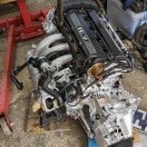
hoodygoodwood 74 3 Cars Posted 6 hours ago I am doing a similar thing to you by stripping my loom back and removing unwanted wires and making one or two repairs before i fit it to my 309 , it was taken out of a 1989 405 Mi16 at the same time as the engine and box etc and i would say it has been cut where it goes through the bulkhead . ECU is 0 261 200 125 and AFM is 0 280 202 202 . The picture shows my 4 way coil plug , the blue wire ( no 2 ) was cut to tee in an imobiliser . Green i believe powers the rev counter and i think would be no 112 in the Haynes wiring diagram . The 2 other wires may be 3A and 2C , i will try to check these . 1 Share this post Link to post Share on other sites
Omorgan 1 1 Cars Posted 6 hours ago (edited) Thank you mate. Looks tidier then my messy wiring are you able to trace where the yellow and pink go please? Edited 6 hours ago by Omorgan Share this post Link to post Share on other sites
hoodygoodwood 74 3 Cars Posted 5 hours ago I will check when i go to the garage tomorrow 1 Share this post Link to post Share on other sites